-edible zone-
3D Print - Otari Feet
Date: 01-20-2024 -- I’ve got a ton of ‘gcode’ that tries to print a functional pair of replacement feet for my Otari reel to reel. As it could be seen, were I to reveal the folder I’m concerned with, there are numerous gcode and .stl files within it. Over the past year +, I've spent no small amount of time trying to get a successful replacement print of the two feet for the Otari MX5050 BII-2 R2R tape machine. The original (oem) feet, (injection molded plastic), had their front noses broken off during the ship. It was 2014 when the deck was returned to me dysfunctional. All funds transferred back to the buyer. eBay. Ship damage. Somewhat later the deck itself was repaired by yours truly and remains operational. I like tape. It’s not the main focus in my audio system, but I like it. And so here I have it.
Do your feet have noses? Nope. They have big toes. But these
feet have noses. Broken noses. They're supposed to stick out ahead
just a bit. Why plastic in the first place? Perhaps its maker wanted
them to be weak. To provide some impact-crunch-cushion? And for
cheapness, naturally. But, really, what was their failure criteria
for this part? These feet are definitely light on build.
 (click thumbnail for full view)

Pause for thought…… I’ve seen one seller on eBay offering his version of these feet made from solid mahogany. That should work, I’d think. But is it a good material strength match? The deck weighs 54 lbs (on my bathroom scales) and these feet take all of that load while being man-handled-this -way-and-that, by its human operators. Which is stronger, the Mahogany or ABS? Should it be a strong foot? In what way? No worry. I'm just floating, hopefully, what's practical. Nevertheless, the plan is to print replacement feet using ABS filament.
First it seems we get to enter the resiny world of industrial plastics. What do you know about plastics? Me, I'll need to take some notes on working with ABS. ABS = Acrylonitrile butadiene styrene. Machinery's Handbook offers an in-depth description of it. And I found a website with more than enough information to satisfy our basic needs to know.
*https://omnexus.specialchem.com/selection-guide/acrylonitrile-butadiene-styrene-abs-plastic
- biodegradeable? No.
- impact resistance = good
- mechanically strong and stable over time
- stress and strain behavior: elongation at Break - 10 - 50%
- Hardness Shore D: 100
- stiffness (flexural modulus) - 1.6 - 2.4 GPa (1.6 GPa to psi = 232060.4)
- Tensile strength: 29.8 - 43 MPa (converts from Mega Pascals to 4322 psi)
- melt temperature: 210 - 270°C
- electrical conductivity= good electrical insulating properties
- Young Modulus (elasticity): 1.79 - 3.2 GPa (1.79 GPa to psi = 259617.55)
- acetone and other solvents, in volume, can melt this material, which can be useful for post print processes that can result in a high gloss finish.
- is easily machined, sanded, glued and painted.
Next we dive into the world of 3d printing with ABS filament. The material -ABS- offers some fair amount of strength along with a certain amount of bend ability – up until that moment just before it breaks into pieces. The automotive industry uses the material for its 5-miles-per-hour bumpers. Myriads of other uses includes outer casework for electronic gadgets such as my old HP 32S-II calculator and numerous other useful shapes.
If you're going to 3D print, you need to start with a three-dimensional solid model. I draw my own. For my cad program I use Rhino 3D. (* footnote) In Rhino, export the model as an .stl file (stereolithography) for the slicer software to create its program, a gcode file.
Here's the model:
* (click thumbnail for full size)
*
Producing any product with this material does require some effort in dealing with the material’s workability. It shrinks during the print. That’s the problem. The other familiar 3d print material, PLA also shrinks a little but not so much as does ABS. But I wanted ABS for the bendability. That bit of elasticity. A bit of flex to go along with its stiffness under load. Then, just after, I did produce a successful (or so it seemed) print using PLA filament. Scroll down below the ABS test to see that result.
Anyway, and at first, the ABS would shrink during the print so much that the ends of this long and slender part pull up off the print bed like the bow of a boat. It's impossible to print with the part laid out lengthwise in contact with the heated bed.
Above image: An early effort. Shrink warped. Not exactly what I drew! Over the course of this adventure I have learned that -with ABS- it helps to turn off the cooling fan setting so that the fan does not run at any time during the print. And this is part of the reason this part wanted to shrink-warp up off the bed. The fans were on. But it's not just about cooling fans. The material itself just wants to shrink during the print. There's gotta be a work-around or the project can't go forward.
To get around the massive end warp, options are to orient the part so that it prints in a vertical or angular config up off the bed. -- Up off the bed being the key phrase.-- So far, 45° nets a workable part with minimal warp along its length. -- It is possible.-- We can get a 3d print replacement for this foot using ABS filament on a Creality Ender 3 Pro printer. Btw this printer commonly sells new at around $180.00 (usd). Mine did, anyway. I'll review the Ender in a seperate report. The subject here is getting a print that works.
Early efforts:
 P4 Crack city.
This is the first near vertical effort. The fans were blowing on this print. That's part of why the part failed. At the time I was thinking that perhaps the support structure, that connecting framework between the two parts, was too strong and as it shrank, it could influence warpage to the part. Or so I thought. So I tried the same layout but with a lighter support structure:
 P4 second try: Failure. The support structure was too light and
would not print. So then there was a third version:
P4 second try: Failure. The support structure was too light and
would not print. So then there was a third version:
 Support design Version 9. This was tried last December after I'd
figured out the business with the fans, so they're off. Bed
temperature is at 110°C. Nozzle temp is at 250°C. Layer
height: 0.15mm. But it too was a failure with cracks along the
layer lines. Actually the cracks were not that obvious but when
held between my two hands the part broke apart under a moderate bending
stress. Failure. So that finally led to the next two designs.
Support design Version 9. This was tried last December after I'd
figured out the business with the fans, so they're off. Bed
temperature is at 110°C. Nozzle temp is at 250°C. Layer
height: 0.15mm. But it too was a failure with cracks along the
layer lines. Actually the cracks were not that obvious but when
held between my two hands the part broke apart under a moderate bending
stress. Failure. So that finally led to the next two designs.
The 30 degree job. My thinking was that - at 30° - you get a longer cross section each printed layer and therefore give the part more time to fuse its layers together than in the near vertical prints. Warpage is minimal.
 P7C - 30° (click thumbnail for full view)
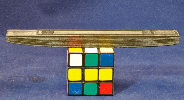
Above screen grab is from Rhino 3D v.5 showing the support system used in part version P7C. The angle off bed was 30°. It is a preliminary view with the part underside on top. I reversed that for the final print. On these elevated prints the underside prints more ragged that it does up topside. This system did print a pair of functional Otari feet. The quality of finish was cobby and rough on the underneath surfaces. The top side print was neat enough. And I did see some support structure break apart in the latter stages of this print. Below is a photo of that print. Red arrow points to the cracked structure.
 P7C - 30° Bed temp: 110°C, Nozzle temp: 260°C. Layer height:
0.15mm.
P7C - 30° Bed temp: 110°C, Nozzle temp: 260°C. Layer height:
0.15mm.
Even though the above printed part was usable I did design another support system that was able to hold together during the print. This time at 45° off the bed. Version P8F.
 P8F - 45°
This version (above P8F) yields the best result so far. Print time was 33 hours and 55 minutes. Layer height: .1mm. Bed temp: 110° C. Nozzle temp: 260° C. Fans = Off. Feed rate at 50 mm / sec
The ABS wants it as hot as this little printer will go. Btw, I’m
using the glass bedplate offered by Creality for this printer.
($20.00) The plate features a carborundum top surface which works as well
with ABS as does regular borosilicate glass coated with wood glue, as I
used to do with my previous printer, a CTI Rep-Rap clone.
Below are
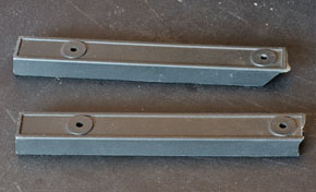
some more photos of version P8F side by side with the original broken
feet.

Above is a group shot of the printed feet next to the broken oem feet. This photo was taken after a little bit of sanding and deburr work. Not pretty, but strong enough. I could have hand-worked the parts more and got a smoother and shiny black surface, but at this stage I’m mostly concerned with function. Function first. Getting them pretty comes second. Besides, the print is still cobby looking and not a final effort. Almost 34 hours of print time, each foot! Then there is hand finish / deburr work to be done. Whew!
(Note to self: 3D printers are not a production tool. They're
for R&D plus mold-making.)


As can be seen in the above two photos, the feet are secured via M4 x .7 machine screws into threaded fittings fixed to the deck’s sheet metal bottom plate. Here I’m using the original screws again.
 (click thumbnail for full view)
Printing these feet using PLA:
I really want to have success using the near vertical orientation as presented in the P9 version seen above and just below. But this time I tried it using PLA filament. And not just any. I used Creality CR series. This according to Creality will produce the results seen when you print the sample figures that came with the printer. Near invisible layer lines with very smooth finish. Good stuff for printing statues and busts of Beethoven, I'd think. But will it print a useful Otari foot?
Rule One; When choosing a 3d Print filiment type, it is advisable to get a material properties summary to avoid ignorance where possible. With that in mind I dug up the following at the linked site just below.
*https://www.xometry.com/resources/3d-printing/pla-3d-printing-filament/
* PLA, what's that name? Poly lactic acid. According to the above source, it's one of the earliest plastics. (circa 1938) Later found to be a biodegradable alternative to PET (circa 1980's). It's been popular with 3D printing over the last two decades. It's made with fermented plant sources such as sugar cane, taro, and corn starch. Definitely, it's biodegradable.
- Tensile Strength: 65 MPa (65 Mega Pascals converts to 9427.5 PSI) (Note this reads high but it's desceptive. Fracture resilliance is poor.)
- Stiffness: rated high
- Max service temp: 52°C, which is low compared to all other polymers
- Durability: Low, Material wears and abrades badly.
- Extruder temp: 190 - 220°C
- Heated Bed temp: 45-65°C
- Stability, Water Tolerance, UV, Chemical resistance: poor
- Ease of printing: easy
- Cosmetic quality: high
*Setting a Failure Criteria for any 3D print filament involves stress loads with regard to the 54 lb weight of the MX5050 BII-2 and in consideration of what type of even-or-uneven surface it might be parked on. However because of this material's poor fracture resilliance, it is obviously not a good choice. Nevertheless I thought I'd see if it would print at all. And it did with the results I have below.
*PLA 1  (click for full size)
*The print appeared successful. No visible cracks along layer lines. But, after I had clipped the parts loose from the support structure, I gave one part a simple 'finger-tip tensile test'.
*PLA 2  Just using fingers and not putting my arms or body into it.
*PLA 3 
*The part snapped apart with minimal effort. And the break was along the layer lines.
*PLA 4 
Well I could make note that I had used the suggested Creality settings as implemented using the Quick-Print settings where you can choose from options like: Creality PLA, Profile = High Quality. That left me with a bed temp of 60°C, nozzle temp of 200°C, and with wall thickness at .8mm, infill is set to 30% with a structure selection of 'lines'. You can see the infill pattern clearly in photo number PLA 3. Lines. These settings did produce a part with as good an appearance as I'd seen using ABS on my best of prints, but not nearly strong enough to use. I know that if I chose a different infil structure, such as 'grid', it would most likely impart greater tensile strength. And I might have set the wall thickness to 1.6mm as I had with the ABS. But I did try those settings with this pla in my early efforts and then lost bed adhesion within the first few milimeters of layer build. Shrink is still a factor when using PLA.
For now, I'll stick to the material that so far has produced a useful printed part. ABS.
So -- this ends the story? Well not really since I figure I’ll use these early prints for now but observe over the next few months as a more complete test. The deck itself could use some sprucing up on its side boards. 1) Either make new boards out of hardwood or 2) perhaps re-upholster the current shabby side boards. An outboard tape head preamp would be an appropriate addition for this tough little Otari.
*footnote: Rhino 3D. I think it's an excellent 3d cad product for the money. In the beginning, a NURBS modeler. Able to produce complex and smooth geometries. You can make sculptures with it. I've been using it since 1998 when it was in beta test and I was part of that group. Then I got my first copy at the cost of an upgrade. Currently using Rhinoceros 5.0 Commercial. They're up to Version 8 at the time I write this.
01/26/2024