-edible zone-
December 5, 2004
Teres Platter upgrade.
The
difference in weight between the solid acrylic platter and the "lead &
acrylic" platter is 12 lbs. The standard platter weighs in at 15 lbs.
Mill the 12 holes, carefully meter in the required amount of #9 lead
shot, seal the hole by threading in solid brass plugs and you get the
lead shot platter that weighs in at 27 lbs. Pretty hefty There are
twelve chambers, spaced equally about the perimeter, that are filled
with #9 lead shot. According to the Teres website, each chamber contains
the same weight value of lead shot to within +- 1 gram. This,
presumably, is so that a balance nightmare doesn't ensue. And none did
according to my ears. The benefit to all this lead shot and brass
weight........? Increased inertia.....which means a more constant rate
of rotation compared to the standard platter. The lead shot within the
chambers is loose so that it may react to resonance within the platter
by resonating itself. The effect is that of a resonant energy drain.
Vibes go in, resonating the lead shot until there is no more energy left
to cause resonance. The spurious energy is fully consumed and dies. We
get a less resonant platter..........and one that spins at a more
constant rate. A goal for all turntables, constant rotational speed.
December 3, 2004
*
Above: Prior to the upgrade --- the now discontinued all acrylic Teres model 135 which I purchased in kit form in 2002. Teres has stopped selling their acrylic base models in favor of various hardwoods. On the other hand, the acrylic platter continues to be a mainstay over at Teres. Personally, I'm not prejudiced against this acrylic.
*
Above: After the lead shot platter upgrade. In the Teres model
line up you add ten points to the model number when the lead&Acrylic
platter is used. This might be the only Teres model 145 in existence.
The lead shot acrylic platter on a plain solid acrylic base. Nothing
plain about it in my eyes.
Teres offers a trade-in upgrade policy
for its customers. I chose to take advantage of this and trade-in my
solid acrylic platter (15 lbs) for the lead shot loaded acrylic platter
(27 lbs). The Teres website refers to this platter as the "Lead&Acrylic"
platter. The cost to me was my old platter/bearing and $500 plus
shipping ($25 UPS Colorado to Washington State) I also have to pay
shipping charges when returning my old platter and bearing within the
same shipping carton back to Teres in Colorado.
* (click thumbnail for full size image)
The platter comes in a plain white 'sturdy enough' corrugated paper box with the "Teres Audio" label that lets you know your goodies have arrived.
*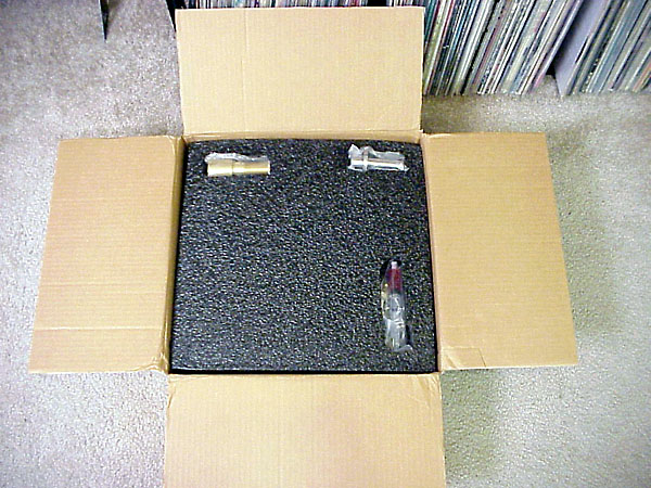
The contents of the plain white box are well insulated from shock and rough handling by way of custom fitted foam inserts. The parts won't move around in there and are well cushioned from accidental impact. Supplied with the new platter is another new platter bearing assembly kit, including a hypo filled with the preferred lubrication. Chris, at Teres supplies new bearings with each platter upgrade in order to match fit each platter and bearing together. Making sure the fit of the platter over the top of the bearing shaft is within a very precise tolerance.
* with top layer of foam removed.
* With second foam layer removed.
This photo does not do this platter justice. Upon opening the box and removing the upper foam protective packing I was greeted with this glistening bit of eye candy. This example in front of me is really something to behold up close and in person. The machine work appears flawless and the polishing work is very well done making this piece look like a work of glass art.
*
Bottom view of the platter up on the kitchen table. This view reveals the threaded brass retaining plugs that secure the lead shot into their chambers. matching threads in each shot chamber allow the plug to screw into the acrylic platter, containing the shot securely. An internal hex machined into the back face of the plug allows the use of a hex key to drive it.
* Long view showing the new platter and the base it would be spinning
upon...quite shortly. I couldn't wait to install the new bearing
which is a time-consuming process, so, I very gingerly fit the new
platter over the old bearing register testing for quality of fit.
It slipped over with about the same snugness of 'slip fit' that the old
platter had. Good match, I thought.
Long view showing the new platter and the base it would be spinning
upon...quite shortly. I couldn't wait to install the new bearing
which is a time-consuming process, so, I very gingerly fit the new
platter over the old bearing register testing for quality of fit.
It slipped over with about the same snugness of 'slip fit' that the old
platter had. Good match, I thought.
* The platter appeared to fit exactly to my base as had the previous one.
Given this news, I chose to re-position the Teres back up on its granite
base steel framed wall rack then do the following:
The platter appeared to fit exactly to my base as had the previous one.
Given this news, I chose to re-position the Teres back up on its granite
base steel framed wall rack then do the following:
- re-connect the pitch sensor to the motor pod
- plug in the interconnects from the tonearm back into the phono stage
- re-connect the bearing ground strap which I have set up with a spade clip disconnect, and.....
- install the mylar drive belt
Ten minutes later I'm spinning vinyl and reveling in the "new music" I now hear. More about the sonic qualities of this upgrade later. Suffice it to say that I was convinced of the value of this upgrade after spinning only a few LPs. Tomorrow I will install the new bearing, I told myself.
_____________________________________________________horizontal rule
*December 4, 2004 (Saturday)
It is now tomorrow. Time to fit
the new bearing. But first I should back up. The UPS driver had
delivered the package at my doorstep from Teres on Thursday Dec. 2nd.
After looking over the pieces in this kit I thought it might be
interesting to check a few things out. In my work day life I am a
mechanical inspector. This means I measure machined aircraft parts to
check for dimensional integrity among other details that control the
manufacturing process. I thought it might be interesting to determine
the actual running clearance between the spinning shaft and the bushing
that holds it.
To begin with I tried to identify the method of
finish on each piece. By visual it appears that the bushing bore is
honed to size. This is identifiable by the tell-tale cross-hatch marks
left within the bore by the honing procedure. The shaft outside diameter
appears to be lathe turned at a very fine feed rate and then hand
polished using progressively finer grits of hand held abrasive media.
Perhaps the final finishing touch was applied with either crocus cloth
or maybe a stick of cratex. (fine cut rubberized abrasive)
When
at work I used a very accurate device called an "air gage" to determine
the inside diameters of the bushing bores. The air gage is manufactured
by Federal and uses a cylindrical plug with air jets. A regulated supply
of air pressure is fed into the plug. The plugs come pre-sized to a
specific range. In this case the plug used could measure .7485 to .7515
inches. With the plug fitted down within the bushing bores air pressure
feedback determines the gap distance between plug surfaces and the bore
surfaces it is within. A highly accurate ( resolution to less than 50
millionths of an inch (0.00005) ) reading shows up on a traditional
needle and dial face. For the OD piece I used a good quality Mitutoyo
electronic digital micrometer to measure the shaft OD.
Results:
Shaft diameters:
- upper register: .7495 inches
- lower register: .7487 inches
Bushing diameters:
- upper register: .7499 inches
- lower register: .7497 inches
The diameter measurements indicate a running clearance at the
upper bushing of .0002 inches (per side) and .0005 inches (per side) at
the lower bush. These figures also reveal what I take to be an
interesting technique. The shaft has .0008 inches of taper reading
smaller at the bottom. I take this to be intentional in order to
facilitate installation of the shaft into the bushing. Keeping in mind
that these are very, very tight running clearances. If there were a
uniform .0002 (per side) clearance straight up, it would be much more
difficult to install the shaft to the bushing by hand. As is, the shaft
will (with care) easily slip into the bushing bore when both are clean
and dry. This was tried lightly and only once as concern about leaving
intrusive marks on either part is paramount.
Surface roughness on
the running fit diameters was measured both to the bushing bores and the
shaft OD using a Taylor Hobson Profilometer. A device that determines
how smooth ( roughness, actually) surfaces on machined parts are by
dragging a diamond stylus across the part for a measured distance. The
stylus is attached to a cantilever, much like a phono cartridge and of
similar size. The movement of the cantilever generates an electric
signal that is read by the circuitry within the instrument to determine
the depths and heights of crests and valleys of the surface on a
microscopic level.
- shaft: 6 micro inches Ra (very smooth)
- bush bore: 23 micro inches Ra (not quite so smooth but still very useable as a bushing bore)
Note: Form check. Roundness checked very good on both of these pieces with no discernable reading variation using the micrometer and less than 50 millionths using the air gage.
______________________________________________________________horizontal rule
So much for brief interludes. Onward with the bearing installation.
I should point out that care should be given that the bearing
housing shoulders up square and flat against its mating surface to the
turntable base. Look for interference of fit between the fillet radius
at the bearing housing and perhaps a sharp corner at the hole in the
turntable base where the housing must fit through. If there is a sharp
corner at the base and a somewhat large-ish fillet radius at the
housing, the sharp corner of the base might make first contact into the
fillet radius and thus prevent the bearing housing from fitting flatly
against the base. A simple test is to simply place the housing loosely
upon its position within the hold in the turntable base. It should fit
flatly without rocking. If this kind of "fit-interference" is seen and
the housing won't sit flat to the turntable base, the fix is to create
an edge break at the top of the hole in the turntable base.
* (click thumbnail to view image full size)
The new bearing receives final torque to its retaining nut. I used a 1-1/2 inch 12 point socket to reach within the counter-bore and drive the nut. A 1/2 inch ratchet handle with adapter (1/2 to 3/4) was used to drive the large socket. Care was given not to "over torque" this retaining nut. The goal was "just enough" torque to seat the bearing permanently to the base. Thought is given to seasonal changes and possible material expansion/contraction. Care is given to ensure that the clear acrylic is not marred by the nut or drive socket during this process. Approximately 10 ft. pounds of force was used. No washers were used between base and nut.
*
Experience with this particular Teres has taught me the value of using the bearing ground strap. This time I know I want it connected. So I do.
*
Final cleaning of the pieces before assembly. Soft cotton wadding is stuck to the end of a pencil by way of tape loop. The cotton is soaked in alcohol before swabbing out the interior of the bushing housing. This is much like cleaning a gun barrel. The process is repeated until.........
*
.......until you can swab out the interior of the bushing bores and not get the cotton dirty any more.
*
Here's a look inside the cleaned Teres bearing housing. My upstairs flat may not be a "NASA clean room" but this bearing housing interior is darn well clean..!
* See Footnote: #1 about the brass bearing ball.
The brass thrust plate and brass ball. Note the white disc fitted to a counter bore within the thrust plate. That's a little pad of Delrin for the ball to spin against. According to Chris Brady, this is the current thrust plate design and has improved wear characteristics over previous thrust plates. He also states that there are some small sonic improvements to be had with these parts. The old bearing in my 2002 model used a teflon coated brass thrust plate and steel ball.
*
All pieces of the bearing assembly have been cleaned and are now ready to assemble. Just looking at the burnished finish on the spindle shaft, it is easy to believe the 6 micro-inch reading taken with the profilometer.
*
The Teres owners manual is referred to prior to installing the lube.
- First, a few drops of lube into the bottom register below the thrust plate
- Then the thrust plate is carefully lowered down to its machined sholder where it mates up. The pencil was used again with a small tape loop to hold the thrust plate and keep it square and the bushing bores undamaged while the thrust plate is inserted. Once the plate is against its shoulder, a slight twist is enough to break adhesion between tape loop and plate.
- Lube is applied to the recess within the spindle tip to hold the brass ball. Just enough lube in there to create a suction between the ball and the close fitting recess it fits within. Then the ball is inserted into its position at the end of the shaft. I get no excess lube over-flow yet the ball appears to be held in by a suction. We don't want this ball to fall out during assembly.......right!
- The remainder of the lube in the syringe (I like the word "hypo") is just enough to fill the well to the very top of the bottom bushing land within the bearing housing. Cool.....we are still operating within the plan.
*
Above: This photo shows the platter already up on the bearing but the bearing hasn't seated against the thrust plate yet. Something like 1/2 inch to go downward. The bearing drop process works as follows:
- With lube already in the bearing housing and the ball fitted to the spindle tip, the spindle is inserted by hand down into the bearing housing. Part way in you can hear air rush out of the cavity as the spindle shaft displaces it. Prior to reaching the puddle of lube, a cushion of air is felt. Like the shaft has made contact with a coil spring.
- Pushing past the cushion of air until the the spindle tip reaches the liquid, a solid hydraulic lock-up is felt. Like it runs into a hard face. Final gasps of air are heard to escape past the spindle shaft and out the housing top. At this point we have a near vacuum within the bearing housing.
- That's as far as we can go by the hand push method. At this point the 27 lbs of platter is used to press the spindle shaft, with ball attached, downward to its thrust plate. The platter is carefully fitted over and into its position on the spindle shaft upper register. The weight of the platter adds down-force upon the shaft to push it downward. As the shaft travels downward, the lubrication in the pool below has no choice but to become displaced around the sides of the shaft and up out the top of the bearing housing where a small pool of lube is allowed to collect in a counterbore at the very top of the bearing housing. Because the clearance between shaft and bearing bore walls is so small (.0002 inches) progress is painstakingly slow.
- In the photo above, a dial indicator is seen. This was added to gain some clues about what rate of travel the ball was making on its journey downward toward its delrin thrust pad. At the beginning I saw .015 inches per minute. Then at one point progress stopped. Complete lock up and there was still 3/8 inch to go. Curious, I added some additional weight on top of the platter to see if this might help. It didn't. In retrospect I assume I had a hydraulic lock up. It wasn't going down any more. This went on for about an hour. Then, carefully I rotated the platter just a fractional amount. Less than a degree. Right then the needle on the dial indicator resumed its sweep and the platter resumed its journey downward. Total trip time was 4 hours and 20 minutes for this bearing drop down onto its thrust plate.
Once the platter was fully home and while the indicator was still set up, I checked the top face of the platter for vertical run-out. My reading was slightly less than .002 inches total indicator reading. Call it .0017 inches. This is better than my previous platter/bearing which measured .003 inches of TIR using the same test procedure.
* (click thumbnail for full size image)
*Checking the gap. Just over 1/8 inch of gap between platter bottom face and top of the turntable base. More like .140 inches. Same as the old platter.
*Not wasting any time, the tonearm was installed to the arm-board and quickly checked for overhang adjustment using a protractor. With platter fitting over the bearing with the same gap distance above the base, and with platter thickness the same as the one it replaced VTA was not a strong concern, but over time was checked and confirmed.
Footnote:
#1: I was surprised to see a brass bearing ball within this kit. Brass is a soft metal and will not wear well when it rubs against a harder material such as the steel of the bearing shaft within the cup at end of shaft. Against my personal judgement I did use it in the initial evaluation of this product. After a short interval I did disassemble the bearing to check to see how the brass ball was holding up. Not well I'm afraid. There was a pronounced flat spot where the bearing ball interfaced within the cup end of the shaft. So I replaced the brass bearing ball with one same size but I chose tool steel with a hardness of HRC 62. After that all worked well.
Also I liked the bearing thrust design which can be appreciated in photos above.
Apart from the brass ball, I was very pleased with the operation of both bearing and platter in this product update.