-edible zone-
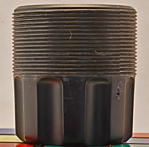
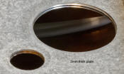
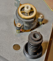
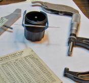
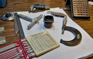
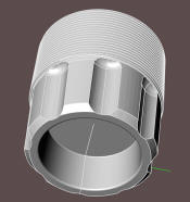
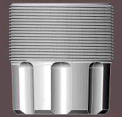
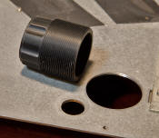
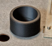
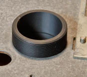
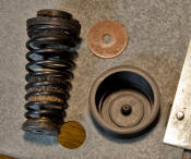
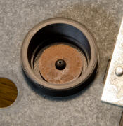
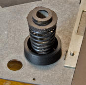
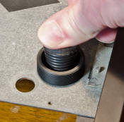
*Above photos: Thorens part number: 6830038. Adjustment Cup. The threads of the cup engage within those of the 2mm thick steel plate. Then that 2mm thick plate - with just 2 threads along its thickness - is what supports the load of the assembled sprung subchassis. For making suspension adjustments, and once the cup is threaded into the plate, turn the cup clockwise or anti-clockwise to raise or lower the floating subchassis at that cup. One of three. Purpose for the adjustment is two-fold: 1) adjust height of the floating subchassis and 2) adjust level of the floating subchassis.
*But why did the designers of the TD126 and it's older sibling, the TD125, resort to this method of subchassis support? 2mm thick steel plate, Plastic cups holding assembled subchassis on its springs. To my mind, the only idea seems to be about isolation. To isolate the subchassis, holding the platter, its bearing and tonearm, from the running motor. Notice in photo 3 above how the motor appears to be machine-screwed directly to the plate.
Well, the plate itself deserves some study. Initial tap tests, with a wooden spoon. Short duration not very loud , higher frequency kind of echo. It appears to have galvanic plating applied. 'Can't say what alloy of steel it is, but a magnet does stick.
4
 (Click thumbnail for full size image.)
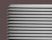
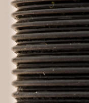
*Above photo 4: A macro detail shot of the oem thread profile. There's something about this that does not resemble the more normal threads one usually sees. Perhaps it's the radiused edges within the thread profile. Actually, this is one od-ball thread. The pitch checks to be 1mm. But you won't find a match to it on any existing thread chart that I can find. At least not with a major diameter of 34.7. Perhaps to think of it as a modified M35 x 1.
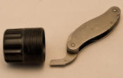
At one point I noticed that the Starrett No. 475 thread pitch gage would just about - but not quite - fit while using the 26 tpi finger gage. And I had to get it under magnification to see the discrepancy. As it turns out, 26 tpi works out to be .0385 inches in pitch. (that's the distance between threads for all of you non-machinists out there) Well a 1mm pitch works out to be .0394 inches. The difference is 0.0009 inches. Which is close. But the 26-tpi finger gage did not exactly fit.
5
 (click thumbnail for full size image)
*Above photo 5: the 26 tpi finger gage did not fit this thread profile. Not quite.
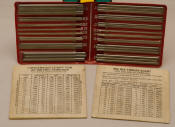
*Above photo 6: PEE DEE wires. Pick the right wire size according to the charts supplied. Use a calibrated OD micrometer to measure over the wires (note: wire size used is .024")
*Above photo: it's an old machinist's trick. Use a rubber band poked with holes to conveniently locate the wires over the threads. Then, using your free two hands, use an OD micrometer to get the read over the wires. Check this in several locations along the threaded feature. Get an average. Take the measurement over wires then subtract the 'constant' according to the supplied chart. This gives you the thread pitch diameter. Which on average is 34.25mm
Oh, and by the way, can anyone out there think of any rare but often mentioned (in certain circles) thread type? Perhaps Whitworth comes to mind? Well Whitworth thread used the 26 tpi pitch. They also used a 55° profile angle. So it could have been used to make this part, but that's not what I get. The threads are metric, not english. This part came out of Lahr, Germany circa 1968, and not Britain in 1936.
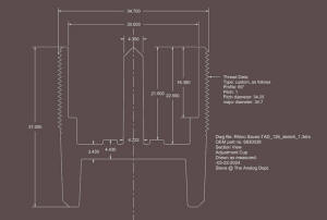
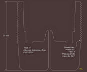
*Above photo: annotated section view of the oem part, as measured by yours truly.
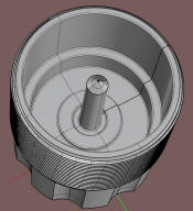
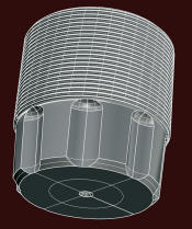
*So what am I doing here? Well, I'm just curious if I can 3d Print one of these..... and have it work! Anyway that's what's going on at this page. So the above section drawing is taken from a freshly drawn solid model.
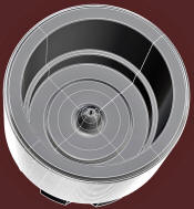
*Above images, the solid model, based on the oem part sample, (click thumbnail for full size )
*Q: But will I print this one? A: No, certain features of this geometry won't print well. So I'll modify the model to suit the needs of my printer.
*Ok what's the problem, why can't you print the oem geometry? Answer: The underneath relief area has no support. Gravity. 3d printers print fine when printing features on top....but not on the underneath bits. Further, that long locator post coming up through the middle seems plenty strong on the oem injection molded parts. But, due to a difference in mass between the center pole and the rest of the part, the center pole, during the print, cools off too fast and fails to get 100% fusion between layers. Ergo, you end up with a center post that looks ok, but easily breaks with minimal finger tip pressure. So I had to change the geometry a bit to get my print to work.
Here's what I drew for the print:
*For this print I'm using ABS black filiment. (1.75mm)
- Slicer settings:
- Layer height: 0.1mm.
- Bed temp: 100°C
- Nozzle temp: 250°C
- Print speed: 50 mm/sec
Here's what I got off the printer:
24
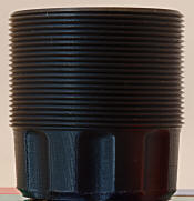 From a few feet away it might not look too scary. But a close-up
photo with a macro lens reveals the layer-by-layer build.
25
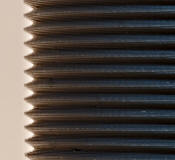 (Click thumbnail to view the printed thread profile)
*Above photo: A macro detail of the printed thread profile. ( Stair-step-city )
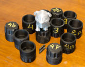
As cobby as the printed part is, it did thread into the plate and give the appearance of strength. With the spring assembly put in place it took some load without signs of distress. Time for a pause. This one - Print 4F- isn't up to standards. I just couldn't resist giving the idea some focus. Meanwhile the three oem adjuster cups seem relatively unworn and smoothly intact.
