-edible zone-
__________________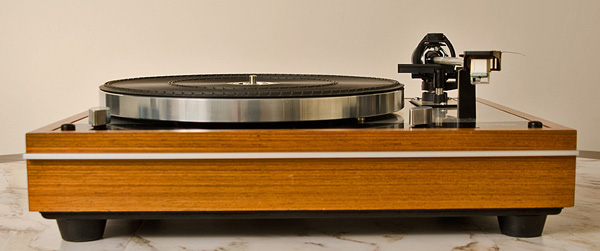
Above photo: 12/9/2015. Just after the
final revisions.
I've undone most of the 'Chadwick mods' I had
carried out on my TD160 several years earlier. After making the
listening observations I have, and in consideration of another
individual (Charles Trayhorn ) recognized as an Audio Professional, I
have decided to take a more conservative approach that employs the best
of Trayhorn's ideas along with what I consider the single most effective
mod carried out by Steven Grant's company known as Chadwick
Modifications.
-- What I'm keeping:
- The more substantial bottom plate. (it was a Chadwick mod)
- The cabinet / plinth, of course
- The Dynamat I applied to the underside of the motorboard
- The RCA jack plate installed to the back of the standard Thorens cabinetry.
- I'm keeping the foam inserts 'out' of the suspensions springs.
-- What I'm undoing:
- The cork / silicone applied to both sides of the suspended subchassis
- Almost all of that Blu-Tak I had applied to the adjoining surfaces of motorboard and cabinet.
- That ridiculous thing I did; covering the outer casing of the motor with blu-tack.
- At one time I had stuffed the underside of the plastic armboard with blu-tack.
- I had put some Dynamat on the top of the motor board that is obscured by the inner platter. That came off.
- That Dynamat I had applied to the underside of the inner platter (hub). Out it came. The Dynamat residue cleaned off nicely with acetone.
- I'm putting the transit locks back into the cabinetry.
-- What I'm doing:
- Using a bituminous felt (a rather stiff version of it I've been able to source) applied to the bottom side of the suspended subchassis.
- Making a new bottom plate. This time with MDF.
- Maintenance on the TP16 tonearm. Disassembly, clean all parts, especially pivot brg cones and cups (with balls) with alcohol and/or acetone, reassemble and adjust pivot bearings.
-- Here are some photos of the TD160C after the 'restoration / modification'.
-- The Subchassis:
*
 (hint: click thumbnail for full image size)
-- Above two photos: The subchassis after the cork/silicone removal. Back to standard....., briefly.
* A photo showing the bared subchassis next to the bituminous felt about
to be applied to it. This 'felt' is very stiff. Very tough. Cuts better
with a saw than by blade.
* After the glue dried. Now I've got a single layer of dampening material
that also happens to stiffen the metal subchassis a tad.
* Oh yes, the adhesive that was used. Dry time takes 48 hours for a
full cure. Pretty strong stuff. Don't inhale. It uses
MEK.
* From the back side the RCA jack plate is seen. I chose American Walnut
for the plate material. I could have used aluminum plate, but chose to
stick with organic materials.
* Close-up view of the jack plate and jacks. Gold plate on brass
connectors with white teflon insulator.
* Looking at the original bottom cover which I assembled to the cabinet
for this photo. The original bottom cover makes an excellent pattern for
making the more substantial cover to be used. Otherwise, it stays off.
* The new bottom cover installed. Material: 1/2" MDF. I deliberately chose
MDF for its audio friendly properties. 1/4-20 thread inserts were
installed and used to secure the large ubber feet. Although cones
are an option, including a three cone pattern, and after considerable
experimentation, I chose the large rubber feet with one at each corner.
* From above looking inside. Note that the transit lock screws have been
installed. I'm retaining the functionality of the transit locks for
practical reasons.
* Looking at the cone foot. It partially covers the counter-sunk screw
that secures the bottom plate to the cabinet. If you want, the four
corner screws can hold rubber feet. The screw hole countersink is made
deep enough so that the cone foot does not make contact with the
fastener screw. Actually, I didn't like the cone feet on this player. I
went with large heavy rubber feet which screwed into the same 1/4-20
inserts. The rubber isolates from the support structure while the cone
feet couple with it so that vibrations can flow between the two
structures through that cone foot. I choose isolation!
-- Assembling the motor board:
* The motor board with subchassis, ready to go in.
*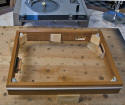 It goes in from this side (top).
* Now it just needs the four fastener screws and we don't forget the four
decorative screw caps.
*


 The flexy black plastic 'snaps' over the screw head.
* Looking in with the turntable inverted. Hook up the speed change shaft.
Install the power cord retainer. Tonearm has yet to be installed.
*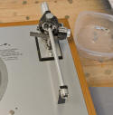 Next: install the tonearm. The TP16 (mk1) will be retained.
But not after a full disassembly, clean, reassemble and pivot brg.
adjust.
*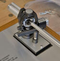 Three mounting screws are now secured.
* Turntable is inverted again. This time with extra care to protect the
exposed tonearm underneath. The cue is operated by a spring loaded
flexible steel cable. The knob in front operates the cable which needs
to be connected to the knob cams.
* Close-up detail showing the cue mechanicals at the tonearm end.
* Tonearm signal wires are soldered to the RCA jacks. The tonearm body
ground wire solders to the ground stud on the jack plate. The
chassis/bearing ground from the ,motorboard tab solders also to the
ground stud at the jack plate. Original Thorens signal wires are
retained. These are extremely fine gage cable and of a low enough
capacitance to be used on even the fussiest of cartridges.
External views: Never mind the cone feet in the photos below. Those are
normally sold for use on speakers and did nothing to improve the sound
quality of this turntable. I went with large rubber feet like these:
* Trying out this Audiosilente precision machined aluminum clutch pulley
(more info on this pulley link&$% )
--Audiosilente - https://www.audiosilente.com/
-- This turntable I pampered all its life. Dustcover is free of any scratches. That's rare for a turntable bought new in 1975. (making me the original owner but note that I sold it in 2015) Do I miss it. Of course. But then there are those other turntables I still have to play with... It never ends.
________________________________________________horizontal rule
-- References:
-- UK. Charles Trayhorn at Metrosound.
Early development of what was to become the Thorens TD160 Super.
-- Trayhorn mods: circa mid 1970's
- remove foam from suspension springs
- motorboard and subchassis damped on underside with bituminous felt
- replaced plastic tonearm board with a high density version left blank to be cut to customer's choice of tonearms
- standard cabinetry replaced with a larger more solid version
- dustcover hinges replaced with metal ones
-- Thorens TD160 Super
-- Thorens essentially used the
above list of 'Trayhorn mods' and based them on its TD160 mkII in AB
configuration. (Came without a tonearm)
--
Chadwick Modifications:
--
"Chadwick Modifications" was the name of the company. Steven C. Grant
operated it in Cambridge, Massachusetts.. And...his middle name was
Chadwick, hence the company name.
*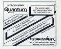 (click thumbnail for full image)
The Chadwick 'mods' carried out
on a Thorens turntable were different from those employed by Trayhorn
and Thorens. He used the standard Thorens cabinetry, but replaced the
thin flexy masonite bottom cover with a far more solid bottom plate made
from 1/2" thick baltic birch plywood. He used silicone damping materials
on the undersides of the motor-board and sub-chassis. He used silicone
also to damp the inside of the inner platter (hub). See below for a list
of mods carried out on a TD125 that was featured in a review by Steven
Stone in TAS vol 14, issue 58, march/april 1989 (pgs 102,105).
Readjustment of tonearm pivot bearings and selectively dampened the arm
tube.
He sold a 'corktone' platter mat and included that in his
list of mods. He offered to replace the standard signal cables with a
Sumiko PIP rca output box and then the customer could use any
interconnect preferred.
End of updates.
