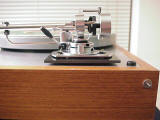
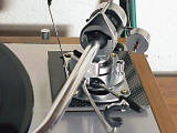
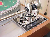
-edible zone-
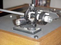
The SME 3009 S2 Improved fixed headshell tonearm. Not
everybody likes this arm. SME had redesigned their vintage S2 series arm
to become a better match to the popular high-compliance,
low-tracking-force, phono cartridges of that day. SME also reduced the
length from the pivot rearward, making the arm a better fit on smaller
belt driven suspended turntables of the time. Perhaps the biggest area
of concern is the nylon knife-edge bearing. Previous models had used a
steel knife edge bearing.
Detractors aside, there are plenty of
these arms in circulation and available second hand. The going prices
aren't terribly high for all the work that goes into the production of
this arm. I thought I might try one and see for myself. Fortunately I
was able to find one that was still sealed in its box. NOS (new old
stock) as they say. Fresh pivot bearings.
Here are some more
reasons I choose this arm.
1) The pivot to spindle requirement
for the SME is the same as for the Thorens arm. This means that the
tonearm should fit within the port opening in the top plate of the
Thorens. Well....you'd think it would, anyway. More about that below.
Besides, SME makes an arm-board for this particular application.
2) I already had a Shure V15VxMR cartridge. The effective mass
rating for the fixed head version of this arm is 6.5grams. This arm will
make a satisfactory match up to the Shure with it's compliant
cantilever.
3) All (most) SME's are lovely to lay your eyes upon,
including this one. It just doesn't hurt to look at from any angle.
Cartridge and Arm matching (link)
Tonearm Alignment definition of terms (link)
Locating the pivot
The SME
3009 Improved does not allow adjustment for effective length. This may
seem somewhat odd to many. Often times, it is the effective length that
is adjusted in order to achieve correct overhang. Not so with this
tonearm. Instead, effective length is a fixed distance and overhang is
aligned by adjusting the pivot to spindle distance. This is fine as both
effective length and pivot to spindle distances are merely adjacent
sides of the same triangle. Given this, it will be important that
sufficient room for maneuvering the pivot to spindle distance is found
within the tonearm mounting that will be arranged.
1)

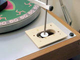
Above photo #1. An early version of the armboard using inexpensive materials to test fit and function. The trammel (A very handy device for measurement of pivot to spindle distance. This being the trammel portion of the Clearaudio protractor ) is used with an extended pointer. Centered to the pointer is a paper disk the same diameter as the outer body of the pivot bearing of the SME. By setting the trammel to the specified 215.4mm length, it can be seen in the photo above and those below that there is indeed open space for this bearing to locate to. There will be no need to grind away any material from the sub-chassis to fit this tonearm. However, the "can" will need to be disassembled from the SME tonearm to make this possible.
2a)
 2b)
2b)
 (click thumbnail for full size image)
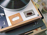
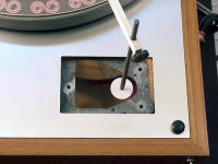
Photo #2a: location for pivot bearing of the standard Tp16 tonearm #2b.
3)
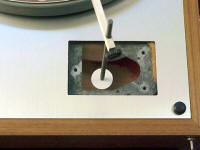 Photo 3: Armboard #2 will use this location for the pivot bearing of the
SME.
_____________horizontal rule
Q: Should this be a one-piece armboard, or could one take a constrained layer approach? Answer below.
____________________horizontal rule
Armboard #2
1)
 (click thumbnail for full size image)
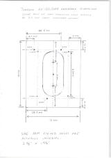
Above, schematic for armboard #2. Thanks to Brian Kearn who has sent in this drawing with dimensions taken from an armboard produced by SME for this very application.
Construction:
Multiple laminates of hobby grade Birch plywood glued together with construction cement except for the top layer which is adhered with four wood screws. If this works to satisfaction, the same layout and build-up technique will be used with better, more suitable grades of materials.
2)

Above photo #2. A final check with trammel for the required pivot to spindle distance. 215.4mm. Even though the mounting distance specification is the same for both the SME and Thorens arms, the mounting plate of the SME tonearm will require a more outward and forward location. So we simply swing the trammel a little further down toward the front. The pivot bearing of the SME arm still fits within the confines of the unmodified Thorens subchassis.
above photo #3: Another trammel photo.
This photo also shows
the thinking behind the layered build-up. The lower portion fits within
the armboard aperture. The top plate that mounts the tonearm rides above
the turntable plinth. The fasteners holding the armboard to the
subchassis are below the upper armboard surface which mounts the arm.
This upper surface is fixed by way of four wood screws that anchor into
the lower layers of this armboard.
above photo 4: Another trammel check this time with the top plate mounted. The top plate, riding above everything, removes from view the port opening in the motor plate. With the tonearm mounted, it would take very close examination to see the nature of the offset.
5)
 (click thumbnail for full size image)
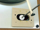
Above photo 5: Another trammel shot that shows the location of the tonearm pivot. Paper disk is same diameter as the body of the bearing pivot in the SME.
Above photo 6: with tonearm mounted.
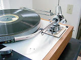
Above photo #7: Side view shows amount of suspension excursion possible with this mounting. It will be enough. One detail which required attention was the length of the mounting screws for the SME. I used #2 x 3/8 brass, slotted round head wood screws.
Armboard #3:
With the second arm board, a functional working layout was realized. This arm board (#3) uses the same dimensional layout as the second board. The trammel is back in its case. Once these pieces were assembled and the arm mounted, a tonearm cartridge alignment was quickly realized. What is different with this board is the material in use. Phenolic. More specifically, Grade LE Garolite Sheet. The material is composed of several layers of a fine weave cotton fabric that is compressed , heated and cured in phenolic resin. The end result is a material with tensile strength figures more comparable to metal than wood. Cuts like it too. It machines readily with metal cutting tools. Definitely harder than wood.
1)
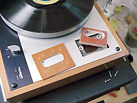
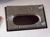
Above photo 1: Retaining the detachable top plate layout as with previous boards. The base layer is 3/8 inch thick phenolic. The top plate is 1/8th inch thick phenolic. The 1/16th inch thick aluminum washers can be seen against the sub-chassis. These three washers are glued into place with neoprene based contact cement.
Above photo two plates prior to assembly
Above photo 3: the base plate phenolic has a top layer of 1/64th inch thick lead sheet. The lead is glued with contact cement. Mounting screws are allowed to make contact with the lead. (note: the lead sheet was not found to be helpful and was eventually removed from the next version armboard
Above photo 4: Top plate is secured with 4 flat head countersunk wood screws. The phenolic material is much harder than wood. Consequently it is necessary to size the screw holes as if it were a tap drill.
Above photo 5: Tonearm is assembled. The suspension has been adjusted. The tonearm is aligned. Ready to go.
6)
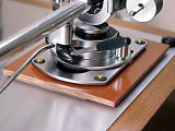 (click thumbnail to view image full size)
Above photo 6: a closeup detail
Armboard No. 4
This is still the layout pattern supplied by Brian Kearns. The main difference between this arm board and the previous arm board No. 3 is that the top plate is now a 1/8 inch thick piece of Carbon Fiber.
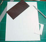
Above photo #1: It always starts with a plan. In this case the plan is a drawing. Using the sketch Brian sent, I worked up a quick CAD drawing. The CAD drawing is useful for supplying a full scale ink jet print out. The Print out is then carefully cut with exact-o knife and straight edge. The 'cut' print out becomes my template for sawing, drilling and filing my parts into final form. In this case the work is 2 dimensional flat pattern style.
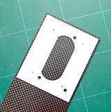
above photo #2: The cut template for the top plate lies on top of the material. I used small strips of drafters masking tape to hold the template in place while tracing the cut lines in permanent ink. In the case of the black Carbon Fiber, the cut template was referred to several times during the cutting process.
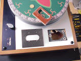
Above photo #3: The pieces just before assembly. The base pad is still Phenolic. The .062 inch thick aluminum washers are still glued down to the sub-chassis from previous board mountings.
Above photo #4: With the base pad in position, the 1/64inch thick lead sheet now visible.* As with board #3, the lead sheet is flatly glued to the Phenolic base pad. It is intended to serve as a damper between the base pad and top plate. Three sheet metal screws secure the base pad to the sub-chassis.*Note. the lead sheet was not found to be helpful and was eventually removed from this version of the armboard.
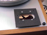
Above photo #5: Armboard is assembled and awaits the SME tonearm. Four screws to hold the carbon fiber top plate firmly to the phenolic base pad. This time I'm using #4 countersunk flat head sheet metal screws to anchor into the phenolic.
Above photo #6: Tonearm is now mounted and aligned
Above photo #7: Suspension is adjusted. Platter is even. Top plate of armboard is level to plinth. Bounce is vertical. Nothing rubs. Sub-chassis floats freely.
Above photo #8: The classic carbon figer look.
Above photo #9: Playing a record.
Final thoughts and notes.
I liked this armboard configuration best of the 4 that I had built.
About the carbon fiber material:
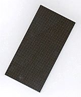
This material is already laid up and cured into a hard plate. Rigid
and strong like steel but light like plastic. The manufacturing process
ensures that the material has excellent flatness.
This
particular piece of CF cost $9.00 from McMaster-Carr. pn# 8181K629 It is
offered as a 'sample'. The sample comes as 3 x 6 x 1/8 inches. Happily,
their sample size makes a TD160 arm board. Many other sizes are
available at drastically higher prices.
Comments about cutting
Carbon Fiber plate
Safety precautions:
Eye protection. Wear a
face mask. The graphite dust generated by the cutting process is extremely
fine and gets into everything and up your nose. I made an effort to
control the spread of this dust. I also kept the shop vac near by and
used it frequently.
Drilling:
Keep your drills sharp. Dull
drills tend to heat up and de-laminate the material. Larger holes can be
pilot drilled in stages to keep cutting pressures small. Choose drills
designed for cutting metals. High speed steel drills are good. Cobalt
drills, better. The material does wear the drills out fairly soon.
Sawing:
Use an abrasive encrusted rod or a blade the same as is
used for sawing fiberglass.
Filing:
The cross sections file
easily with metal cutting files.
Comments about cutting grade LE
Phenolic:
Use metal cutting tools. The material cuts cleanly and
easily but with significantly more resistance against the cut than does
common hardwood. Softer than aluminum, harder than wood. The cutting
process releases a strong ammonia smell that burns and waters the eyes,
irritates the throat and offends the nostrils. Don't breath the fumes.
Otherwise, it's just unpleasant.


